

Analytix Cams - 机械工程仿真软件
Analytix Cams使机械工程师能够根据其从动件运动要求快速合成凸轮轮廓。或者从现有的凸轮轮廓,从动件的几何和运动学可以快速设计,微调和分析。分析包括运动、静态、动态、逆动态和公差分析。随着Analytix模拟软件,可以优化凸轮/从动件与机械系统的交互。然后将DXF导出到CAD或将坐标数据导出到NC/CAM软件。
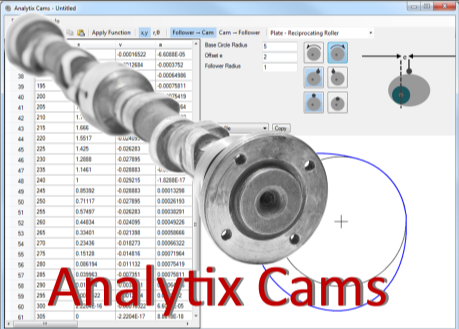
以下是如何使用Analytix Cams来合成凸轮轮廓。开始,选择凸轮/从动件类型以及旋转方向和从动件偏移等内容。然后选择凸轮旋转范围,指定从动件位移的开始和结束要求,以及所需的曲线类型(如摆线、停顿或恒定加速度)。
然后,Analytix/Cams会自动合成其间的准确点,并考虑该凸轮/从动件配置中涉及的全部几何图形。
例如,您可以指定从动轮角度应该具有在凸轮旋转0度和90度之间的35度修正梯形上升,依此类推。高等用户始终可以选择手动微调数据点(或从其他来源插入数据点)。
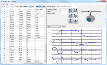
运动学和其他数据自动计算,并以表格和图形形式显示:位移,速度,加速度和曲率半径。
在Analytix Cams中开发的任意凸轮轮廓也可以在Analytix mechanical simulation软件中使用,以结合更大机械系统的执行器、连杆或其他零件来分析凸轮运动。
凸轮设计和机构分析可以在一个负担得起的集成解决方案中快速完成,使您可以从所需的末端执行器运动返回到凸轮/从动件设计,反之亦然。

规格
凸轮类型
-
Plate -- oscillating roller follower
-
Plate -- oscillating flat-face follower
-
Plate -- reciprocating roller follower
-
Plate -- reciprocating flat-face follower
-
Linear -- oscillating roller follower
-
Linear -- reciprocating roller follower
-
Barrel -- oscillating roller follower
-
Barrel -- reciprocating roller follower
用法
-
从动件到凸轮的方法?是的
-
凸轮到从动件的方法?是的
-
模拟较大机构内部(是的,使用Analytix)
运动合成功能
-
Dwell
-
恒定速度/加速度
-
摆线
-
修正谐波
-
修正梯形
-
修正正弦
-
345-多项式
-
4567-多项式
数字表格和图表
-
凸轮轮廓(x-y或r-theta)
-
移位
-
速度
-
加速度
-
jerk
-
S-V-A-J
-
压力角
-
曲率半径
几何选项
-
顺时针/逆时针
-
左/右
-
基圆半径/角度
-
初始角度
-
从动臂长度
-
枢轴距离/坐标
-
左/右偏移尺寸
-
上/下随动件
-
Barrel半径
-
从动件半径
数据交换
-
DXF交换
-
X-Y或R-Theta坐标,制表符分隔的导入/导出
-
Windows复制并粘贴到Excel
【英文介绍】
Analytix Cams enables mechanical engineers to quickly synthesize a cam profile given their follower motion requirements. Or...from an existing cam profile, the follower's geometry and kinematics can be quickly designed, fine-tuned and analyzed. With Analytix simulation software, you can optimize the cam/follower interaction with your mechanical system. Then export DXF to CAD or coordinate data to NC/CAM software.
Here's how Analytix Cams is used to synthesize a cam profile. First, you choose the cam/follower type and such things as direction of rotation and follower offset. Then select a range of cam rotation, specify the starting and ending requirements for follower displacement, and the desired curve type (such as cycloidal, dwell, or constant acceleration).
Analytix/Cams then automatically synthesizes the precise points in between, taking into account all the geometry involved in that particular cam/follower configuration.
For example, you can specify that the follower angle should have a modified trapezoidal rise of 35 degrees between 0 and 90 degrees of cam rotation and so on. The advanced user always has the option of fine-tuning the data points manually (or inserting them from another source).
Kinematic and other data is automatically calculated and displayed in both tabular form and graphical form: displacement, velocity, acceleration, jerk, radius of curvature and pressure angle.
Any cam profile developed in Analytix Cams can also be used inside Analytix mechanical simulation software to analyze the cam motion in combination with actuators, linkages, or other parts of a larger mechanical system.
Cam design and mechanism analysis can be done quickly in an affordable, integrated solution, letting you work back from required end-effector motion to cam/follower design or vice versa.


- 2026-06-25
- 2026-06-25
- 2026-06-24
- 2026-06-22
- 2026-06-22
- 2026-06-18

- 2026-06-30
- 2026-06-22
- 2026-06-22
- 2026-06-22
- 2026-06-11
- 2026-06-11